- Physics Review
- Instrumentation for planar radiography
- X-ray image quality
- Radiation dose and exposure
- Specialized x-ray techniques and clinical applications
- Radiation oncology applications
Physics Review
Knowledge of the underlying physics is important for understanding how x-ray and other photon imaging systems work.
Photon interactions
An example of the electromagnetic spectrum is shown below. X-ray imaging falls into the “x-ray” part of the spectrum, where the wavelength and frequency correspond to the size of atoms. X-rays are photons that are generated from accelerating electrons or transitions of electrons in atoms. X-rays are typically in the 100 eV to ~MeV energy range, but for medical imaging are within 30-150 keV. (Contrasted with gamma rays, which are used in Nuclear Medicine, which originate from nuclear reactions and energy transitions within the nucleus of an atom and are usually higher energy.)
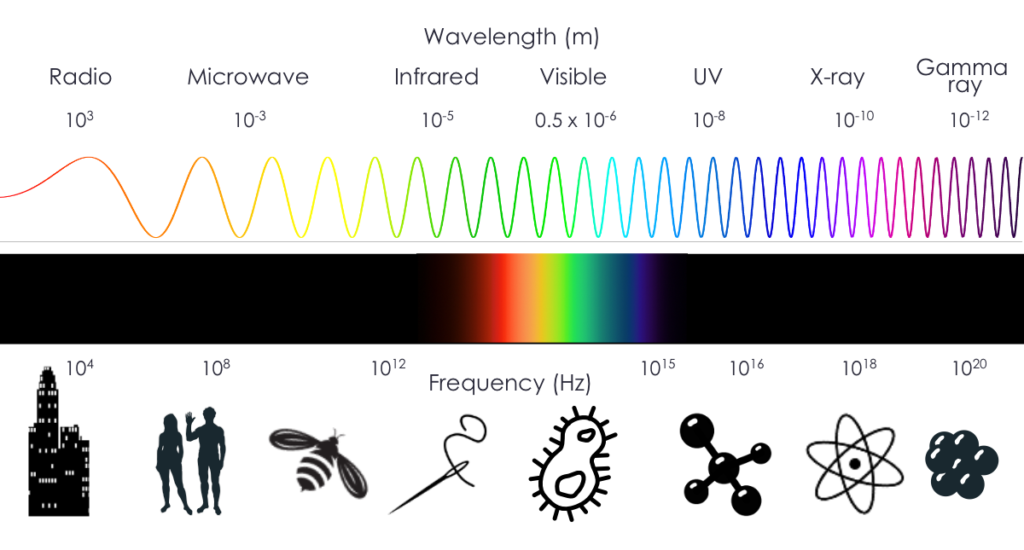
Wave-particle duality and the relationship between speed of light (c), wavelength (λ), frequency (ν) and energy (E):
\(c=λν\)
\(E=hν=hc/λ\)
\(E=mc^2\)
h is Planck’s constant, a fundamental constant with a value of h = 6.62607015×10⁻³⁴ J⋅Hz−1 . It is used to translate between energy and frequency.
The two main types of interactions for photons in medical imaging are photoelectric (PE) and Compton. PE interactions happen when a photon is absorbed and knocks out an inner shell electron, and there is a resulting cascade of photons as electrons from higher shells drop down to fill the inner shells. Compton scattering happens when the photon interacts with an outer shell electron. The electron is ejected and the photon is deflected and loses energy such that \(E_0 = E_{sc} + E_e\) (energy must be conserved).
The probability of photoelectric interactions is proportional to the density (ρ) and to the cube of the effective atomic number (\(Z_{\text{eff}}\)) of the material the photon is passing through and inversely proportional to the cube of the energy (E) of the photon:
\[P_{pe} ∝ ρ Z^3/E^3\]
This relationship means that as the atomic number increases, PE interactions are much more common. As the energy of the photon increases, PE interactions are much less common. This is an important effect in several aspects of medical imaging.
Compton scattering becomes more common as photon energies increase and the atomic number of the material decreases. Thus for most x-rays in soft tissue, Compton scattering is the dominant interaction.
Attenuation
Attenuation is the basis of image contrast in x-ray and CT imaging. It is the ratio of photons sent into a material to those that pass through and reach the detector (i.e. the ratio of photon intensities). Photons that don’t make it through the material likely undergo photoelectric or Compton interactions. Anything that stops or diverts the photons contributes to attenuation.
Mathematically:
\[I = I_0 e^{-μ(E)x}\]
where I0 is the initial intensity, I is the transmitted intensity, x is the object thickness and μ(E) is the energy-dependent linear attenuation coefficient. The linear attenuation coefficient depends on the atomic number and density of the material and can be looked up in tables of materials and energies. Higher density and higher Z materials will attenuate more photons.
Instrumentation for planar radiography
Planar x-ray radiography is the most common radiology procedure. It is often used for first screening for acute injuries, suspected diseases. It is fast, cheap, and low radiation dose. It is excellent at detecting bone fractures, masses in lungs, kidney stones, etc. The contrast in the images comes from how different materials cause a differing amount of photon attenuation. For instance, bones and calcification absorb x-rays more effectively than soft tissue, while soft tissue will attenuate more than air-filled lung.
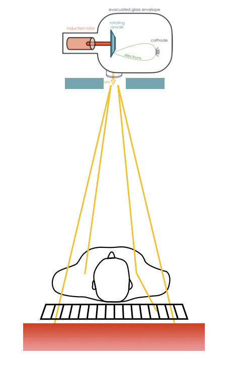
X-ray imaging is based on transmission detection. X-ray photons from a source are sent through the patient, and those not attenuated are collected by a detector on the opposite side. That detector can then be used to form an image. Years ago, those detectors were film, similar to photography film, but are now most commonly a digital system.
X-ray tube
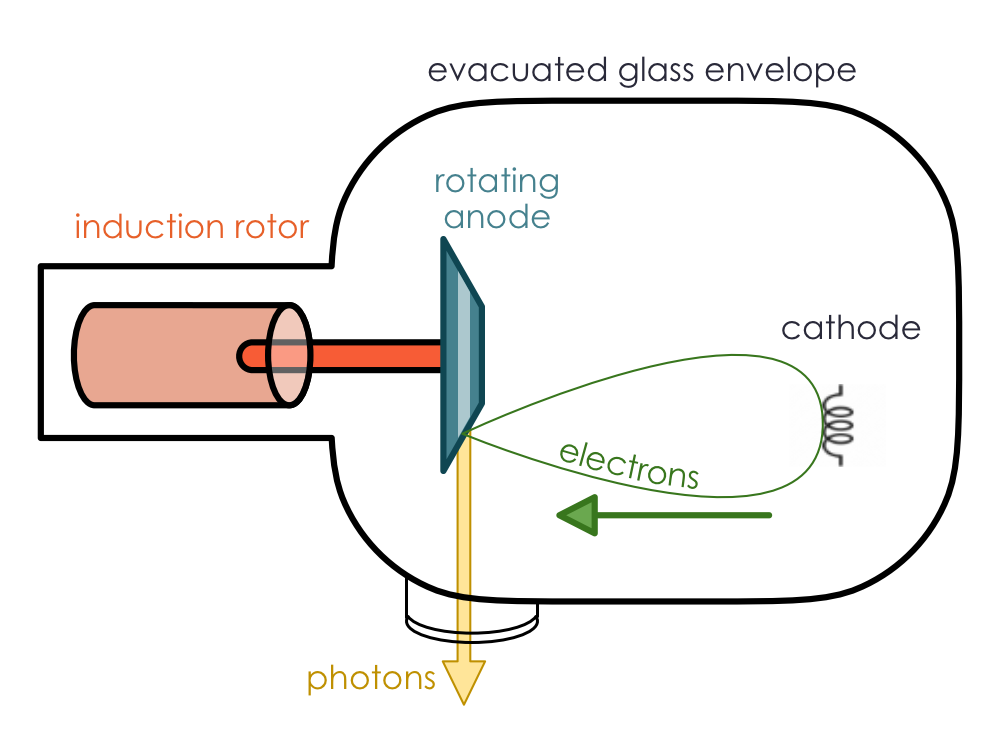
The source of photons in an x-ray imaging system is an x-ray tube. The basic parts and configuration of an x-ray tube are shown to the right.
All of the main parts are in an evacuated glass envelope surrounded by cooling oil and lead shielding (not shown). A small coil of wire called the filament acts as the cathode. It is heated until electrons are released from the metal (thermionic emission, sometimes called “boiling off”). An electric field accelerates these electrons and directs them to a copper anode (positively charged electrode) that spins with the help of an induction rotor. The electrons hit a tungsten target on the angled anode which generates x-rays. Those x-rays exit the tube through a thin beryllium window in the shielding.
The tube generates kilovoltage (kV) x-rays suitable for imaging (i.e., high enough energy for many of the photons to pass through a patient, but not so high energy that all of them pass through). The main process through which most x-ray tubes generate kV photons is through bremsstrahlung. Some characteristic x-rays also contribute to the x-ray beam, but they are are a small proportion (one exception is mammography, which is designed to enhance the characteristic x-rays).
Bremsstrahlung (a.k.a. “breaking radiation”) is radiation produced by acceleration of charged particles, typically around an atomic nucleus. In this case, the electrons sent from the cathode into the anode target are deflected by the tungsten nuclei and lose some energy. Because energy must be conserved, photons are produced in a continuous spectrum. That means that the photons produced can be any energy from zero up to the energy of the electrons. The energy of the photons produced increases as the electrons pass closer to the nucleus, but closer interactions are rarer. The number of photons coming from the anode is roughly inversely proportional to the energy.
Characteristic x-rays are produced when an electron is ejected from one of the electron shells, and orbital electrons drop to fill the lower energy shell. Photons are emitted with energy equal to the energy difference between the shells (conservation of energy). Characteristic x-rays are only produced at discrete sets of energies, unique to each atom. Tungsten mostly produces photons of 69 keV, 10.2-12.1 keV and 1.0 – 2.8 keV depending on which electron shells are involved.
| Characteristic radiation | Bremsstrahlung |
|---|---|
| Small percent of x-rays produced by tube | Accounts for > 80% of photons in an x-ray beam |
| Incoming electron interacts with inner shell electron | Incoming electron interacts with entire atom |
| Radiation is released when an electron drops from a higher to lower energy state | Radiation is released when the incoming electron is accelerated around an atom, to conserve energy |
The spectrum from an x-ray tube is the combination of Bremsstrahlung and characteristic x-rays, with Bremsstrahlung contributing to over 90% of the photons in most systems. In addition, low energy x-rays are filtered out, partly from the beryllium exit window and an additional aluminum-based filter to remove additional low energy x-rays. The filtering is important to reduce radiation dose to the patient, especially since those low energy photons would not pass through the patient to be detected.
X-rays settings are characterized by the maximum (peak) energy of the photons that are produced, denoted kVp. The peak energy is determined by the peak energy of the electrons that hit the target (they cannot give more energy than they have). This value is often offered in discrete values such as 80, 100, 120, 140 kVp, and is controlled by the electric field between the cathode and anode. The average energy of the photons is typically 1/3 to 1/2 the kVp (depending on filtering), and the weighted average energy is about 2/3 the kVp. Changing the kVp has implications for the image quality and dose, discussed below.
Heat
Earlier, it was noted that the anode spins. Only about 1% of the electrons hitting the target produce photons; the rest produce heat. The spinning of the anode presents a larger surface area to target, thus dissipating heat without creating a larger beam. The copper of the anode and the oil bath around the tube both also help dissipate heat. In addition to being high Z (good for producing Bremsstrahlung), tungsten also has a high melting point, making it an ideal target material.
Source size
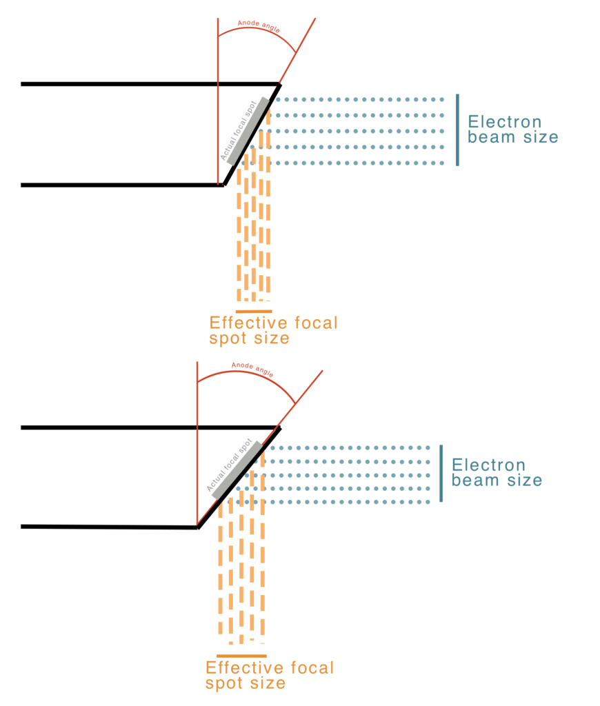
The size of the x-ray source has important implications for image quality. A smaller source will have better spatial resolution, but smaller sources also mean smaller fields of view. The beam size is reduced in one direction by a electrical focusing cup around the filament coil, but the length of the coil limits the size in the other direction. The filament size and bevel angle of the anode determine the effective focal spot size and, thus resolution: \(f = F \sin(\theta)\). See diagram for an illustration of the geometry, where \(\theta\) is typically 8 to 17 degrees. The angled anode allows for a small effective spot size with a larger actual spot size (i.e., filament size) and better heating distribution. The field of view coverage is governed by \(\text{FOV} = 2 \times \text{patient distance} \times \tan(\theta)\). Many systems have two different filament lengths for different applications but a fixed anode angle.
A large anode angle with a small filament yields large field coverage and a small effective focal spot, but poor power loading (meaning excess heating). A large anode angle and long filament length yields large field coverage and a large effective focal spot (poorer resolution, but good power loading. A small anode angle and long filament length yields small field coverage, a small effective focal spot, and good power loading. As you can see there are trade offs for the various configurations, generally among heating, field of view, and resolution.
The clinical task can govern the most appropriate system and settings to use. For instance, imaging of the pelvis likely requires a large field of view, but resolution might not need to be great, whereas visualizing a hairline fracture in a foot or a mammography exam require very high resolution, but need a much smaller field of view. For mammography the typical spot size is 0.3 mm while for general planar and CT imaging, the spot size is usually 0.6 – 1.2 mm.
Tube parameters
In most x-ray systems there are three main parameters chosen by the operator:
- Accelerating voltage (kVp)
- This is the voltage used to accelerate electrons to the anode. It governs their final energy and the peak energy of the Bremsstrahlung photons.
- Tube current (mA)
- This is the current of electrons flowing from cathode to anode, and related to the current in the filament used to boil off electrons. It governs how many photons are produced
- Exposure time (s)
- This is the amount of time that the current is flowing. It is often multiplied by current to get “mAs”, i.e., total charge delivered and related to the number of photons sent through the patient.
These settings control image quality and radiation dose to the patient.
kVp
Peak kilovoltage affects image quality in a couple ways. Too low and not enough photons can penetrate the tissue. This leads to dose to the patient but noisy images. This is especially a problem for larger patients and wider body parts. For smaller body parts, e.g., compressed breast tissue or extremities, lower kVp is okay. Too high kVp means that there are fewer photoelectric interactions. Because photoelectric interactions are highly dependent on atomic number, Z, they are useful to distinguish different tissue types. If as more interactions become Compton interactions, it is harder to get contrast between tissues. The sweet spot for kVp is typically between 80 and 140 kVp.
mAs
Tube current (mA) and exposure time (s) are often combined into “mAs”. This value is directly related to the number of photons sent through the patient. As such, higher mAs leads to higher radiation doses, but also better images (less noisy). mAs are chosen to balance dose and image quality. Higher mAs may be needed for wider body parts (more attenuation) to ensure enough photons reach the detector.
Other components
Between the x-ray tube and the photon detector, there are several other components that are used to improve image quality and control the patient dose. Scattered photons are a major source of lowered image quality and increased patient dose. Collimators and anti-scatter grids are placed before and after the patient to reduce the effect of scatter.
Collimators
Collimators are typically lead sheets placed near the x-ray tube and restrict the dimensions of the beam to the imaging FOV. For a rectangular field, both directions can be controlled independently, and a visible light field is often available to help with positioning. The light is shone through the collimator onto the patient, and the collimator is adjusted to cover only the body parts needing imaging. Positive beam limitation (PBL) collimators will automatically limit the field size to the useful area of the detector.
Reducing the beam size means fewer unwanted photons that only contribute to dose to the patient and scatter into the useful field of view.
Anti-scatter grids
Anti-scatter grids are thin lead septa placed between the patient and the detector. They are oriented along the x-ray beam, allowing most unscattered rays to pass while blocking most scattered rays. They can be either parallel or focused (to match the beam spread). The reduction in scattering depends on the thickness, length, and separation of the septa.
Unfortunately, the septa will also stop some unscattered rays. As such, the number of photons, and thus the dose, needs to be increased to maintain the same noise level. The “Bucky factor” (BF) characterizes the tradeoff between increased contrast and the additional dose needed for the same noise levels.
B = incident / transmitted photons
The value of B depends on the grid ratio (height / separation of septa) and the kVp used. The value is typically between 4 and 10, meaning up to 10x as much dose is needed, but the reduction of scatter can greatly improve image contrast.
AEC
Automatic exposure control (AEC) is often used to ensure optimal balance between image quality and dose. Sensors (typically ionization chambers) are placed between the patient and the detector. They measure the actual radiation incident on the detector. That measurement is fed back into the x-ray tube control and adjusts the current and exposure time (mAs) to keep a desired dose level. The AEC effectively accounts for the patient size and density to maintain a consistent SNR.
It is important to place these sensors behind the patient but not behind any metal implants. Metal implants are highly attenuating and stop photons so efficiently that the sensor feedback will tell the x-ray tube to keep irradiating because they exposure is too low, even through other parts of the body have had more than enough.
X-ray detectors
X-rays are more difficult to detect than visible light because they are much higher energy and higher energy photons are less likely to interact with a detector. There needs to be some sort of interaction between the photon and detector to get a signal.
The typical strategy with modern detectors is to convert x-rays to visible light or electrons and then detect those.
Analog Film
Film for x-rays works similar to visible light on photographic film. X-rays interact with silver atoms in the film. The sensitivity of film to radiation depends on the concentration and size of the silver halide grains used. Often intensifying screens will be used on either side of the film to increase the amount of light. Thicker screens add more light, but also allow light to spread more, and thus reduce spatial resolution.
Film is rarely every used for x-rays anymore, because of the need to develop the film with chemicals, and because it is not possible to adjust the contrast after exposure and development, a huge advantage of digital imaging. It does however allow for imaging a large area at once relatively cheaply, and it has excellent spatial resolution. Spatial resolution depends in part on the detector element size, and in the case of film, those elements are around the size of the silver halide grains (1 to 1.5 um).
CCD and CMOS
Charge-couple devices (CCD) convert film to a digital format. They measure the light transmitted through the film as the film is passed through a slit in the device. A lens focuses the image onto a charge-coupled device which store the signal an electric charge until it is read out by an analog to digital converter. The digital image is formed based on the optical density \(OD = log_{10}(I_0/I)\) where \(I_0\) is the initial intensity and \(I\) is the intensity after passing through the film.
Complementary Metal-Oxide Semiconductors (CMOS) are light sensitive arrays and an alternative to CCD arrays. They have a crystalline silicon matrix and a small size (10 x 15 cm). RAM “chips” with photosensitive detectors and readout electronics. It is possible to randomly access any detector element to read or erase, and allows for automatic exposure control.
Computed Radiography (CR)
Computed radiography uses a flexible imaging plate instead of film to capture images. The detector plate is placed within a cassette and a CR reader is used to digitize the image. The plate is made of photostimulable phosphor (PSP) as a thin layer (0.1-0.3 mm) of phosphor crystals (e.g., BaFBr(Eu)). X-ray energy releases electrons on PSP, which become ”trapped” in extra energy levels in the lattice of crystals. This is called a latent image which is stored in the PSP and later read out. Images are made visible with a CR reader consisting of lasers which free electrons from the traps. When they are freed, the plate emits blue light that is detected by lenses and photodiodes. The signal is then converted to voltages, amplified, filtered, and digitized. Thinner layers and smaller crystals are used for higher resolution. This is a semi-digital system and can be used with low doses. It has advantages over film in that it is possible to see the image quickly, no need for chemicals, the detector plate is reusable and it is insensitive to visible light. However, the ability to adjust for under/over-exposure is limited and the cassette must be positioned and replaced for each exposure.
Digital Radiography (DR)
Digital Radiography has become one of the most common x-ray detectors. One of the main advantages of DR is the ability to adjust for under/over-exposure. There are two main types: indirect and direct.
Indirect flat panel detectors are the most common. X-rays are absorbed in a scintillator which produces visible light when struck by x-rays. That visible light is then converted into electrons using electronics and a thin-film transistor array (TFT). In direct flat-panel detectors, x-rays are absorbed in a photoconductor and converted directly to electrons, skipping the step where the x-rays are converted to visible light.
Indirect FPDs use scintillating crystals (e.g. CsI) to convert x-rays to visible light and a TFT to convert to an electrical signal. The detector is structured into pixel (“dexel“) elements using lithographic etching techniques to deposit electronic components and connections. These include amorphous silicon photodiodes, capacitors to store charge, and a TFT switch to read out the capacitor and produce a voltage signal. That voltage is then digitized and converted into an image.
Direct FPDs skip the part of converting the high-energy x-rays to low-energy light photons. Instead, the x-rays are absorbed by a photoconductor (e.g. amorphous selenium or a-Se). The photoconductor converts x-ray energy into free electrical charges. The charges are collected in capacitors to create a latent image read out via TFT switches, which produce a voltage. That voltage is then digitized and converted into an image.
Comparison
Advantages of DR
- Generally more flexible
- More range in contrast
- Can adjust for over/under-exposure
- Digital image is electronic
- Quantified by brightness level (luminance)
- Can manipulate display contrast
- Can perform quantitative analysis
- Decreased radiation exposure for same image quality
- Fast imaging process (instant display)
- No toxic chemicals
Disadvantages of DR
- DR systems more expensive than film
- Worse spatial resolution (readout pixels vs silver halide grains)
X-ray summary / chart
- X-rays produced in x-ray tube
- Electrons boiled off cathode, accelerated to anode target. Photons created through bremsstrahlung (most) and characteristic x-rays (few).
- Collimator limits FOV, reduces scatter and dose
- X-rays pass through patient, some are attenuated (do not reach detector)
- Different tissue types, thicknesses and densities have different amounts of attenuation and create the contrast in the image
- Anti-scatter grid stops scattered x-rays to improve contrast
- X-rays strike detector which converts them into an image
- Film is developed
- DR converts voltage signals using a ADC and generates digital image
- Image is displayed and post-processed
X-ray image quality
SNR
Radiation is stochastic, meaning it is a random process with a probability distribution, for both emission and detection. One can analyze events statistically, but it is not precisely predictive. For a given photon we cannot say how it will interact with an atom it encounters, only the likelihood of a set of possible interactions. A 100 keV photon might be 100x more likely to undergo a Compton interaction, but it will still undergo a photoelectric interaction once in a while. These statistical fluctuations are a form a noise that becomes part of the images. Mathematically, the most important relationship to note is that for N number of events, the uncertainty is σ ~ √N. That is, the standard deviation of the distribution of events is statistically equal to √N. This means that SNR ~ √N and thus to double the SNR of an x-ray image, one must have 4x the events, which means 4x the dose!
Practically, SNR is affected by the tube current (mA) and the exposure time (s). These two parameters, often combined into mAs, govern the number of photons being sent from the x-ray tube in linear relationships. Double the current, double the photons. Double the exposure time, double the photons. Double the mAs, double the photons. The tube voltage affects the number of detected x-rays, since higher energy photons are more likely be transmitted through the patient (not be attenuated). This effect is not linear and depends on the exact x-ray tube spectrum and patient characteristics.
Likewise the size and composition of the patient and parts being image affect the attenuation and number of photons reaching the detector. Other components, such as the anti-scatter grid also add attenuation and limit the number of detected photons and thus affect SNR.
Finally, detector efficiency also plays a role in the SNR of an x-ray image. Essentially, the more likely a photon is to be stopped by the detector and converted into an electrical signal, the higher the SNR will become. The “detective quantum efficiency” DQE of a system is always less than 1 and is described by the square of the SNR coming into the detector divided by the square of the SNR coming out of the system: \(\text{DQE} = \left(\frac{SNR_{out}}{SNR_{in}}\right)^{2}\)
Spatial Resolution
The main factors that affect spatial resolution in x-ray imaging are the tube filament size, the anode angle, distances, and the detector configuration.
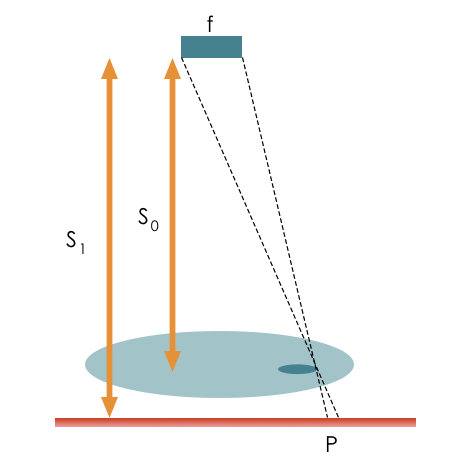
The larger the focal spot size, the worse the resolution. Spot size is determined by the filament size and anode angle. Increasing the anode angle or reducing filament size will improve resolution by creating a smaller spot size. The relative distance of the tube to the patient \(S_0\) and the patient to the detector \(S_1\), also affect resolution, and the penumbra causes blurring at the edges (see magnification below). \(P = \frac{{f(S_1 – S_0)}}{{S_0}}\)
The properties of detector also affect resolution. As noted above film has great resolution because the detector elements are on the order of molecules in size. For digital detectors, the size of the detector elements limits the image resolution. Likewise, the geometry and physical composition affects the resolution. As the thickness of scintillating detectors increase, there is a greater chance for light to spread and worsen the resolution. Direct digital detectors use scintillation and thus can achieve higher resolutions.
Patient motion will also affect the apparent resolution. Smaller objects will be harder to see if they move between pixels during the exposure.
Magnification
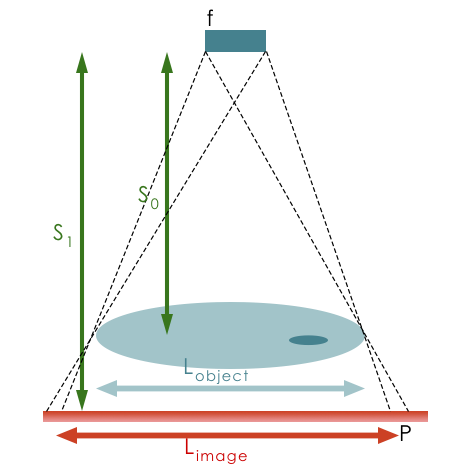
Projected objects will be magnified depending on source-to-object distance and object-to-imager distance.
\(m = \frac{{L_{image}}}{{L_{object}}} = \frac{{S_1}}{{S_0}}\) where \(S_0\) is the source to detector distance and \(S_1\) is the object to detector distance.
Objects further from the imager will have blurrier edges. Usually, a radiographer will try to keep the object as close to the detector as possible.
CNR
There are two major components of contrast: contrast inherent in the subject, coming from how different tissues will attenuate photons in different amounts, and detector contrast, how well the detector is able to distinguish between different photon intensities.
Film can be designed with different latitudes and dynamic ranges (how good the film is at distinguishing between different numbers of photons). Contrast can be lost by under or overexposing the film. Contrast is proportional to difference in optical densities: \(C \propto OD_2 – OD_2\)
For CR/DR there is in intrinsic contrast like for film. The electron concentrations are proportional to exposure and conttrast comes from difference in pixel values: \(C = PV_1 – PV_2\). Because these are digitized, post-processing can be used to adjust apparent contrast, and display contrast can be adjusted using different windows/levels.
Practically, contrast is affected by the X-ray spectrum (kVp) of the x-ray tube. This comes back to the different contributions of Compton and photoelectric effects. The photoelectric effect dominates at low energies and is much more likely for bone than soft tissue, likelihood ~ \(Z_3/E_3\). Compton dominates at higher energies and has a low dependence on atomic number. As a result, contrast can be improved by reducing the kVp, but at the same time, lower kVp can result in more noise since more photons are attenuated. Contrast is also affected by scattering. The amount of collimation, the design of the anti-scatter grid, and the thickness of the body part all affect the scatter and thus the contrast. More collimation, higher grid factor, and thinner body parts all result in less scatter.
Contrast agents
Sometimes the inherent subject contrast between two tissues is very low (i.e. they have similar density and effective atomic number, Z). External substances can be introduced into the body to enhance the contrast. These contrast agents are typically injected or ingested and add material with higher density and Z. The contrast material circulates and accumulates in the body in particular organs or structures. The presence of the contrast agent enhances subject contrast between the region of accumulation and surrounding tissue. These are used in x-ray, CT, US, MRI. Ideally, they should have little physiological effect, although allergic reactions are possible and renal disease might impair clearance, so they cannot be used in all patients. For x-rays, a high-Z material such as barium (Z = 56, k-edge 37.4 keV) and iodine (Z = 53, k-edge 33.2 keV) are used to increase the likelihood of photoelectric interactions (~\(Z^3/E^3\)). Because they are attenuating, they will appear bright on x-ray image (similar to bone).
Oral solutions with barium are used to visualize GI tract. IV solutions with iodine are used to visualize vessels. Depending on how long after injection the images are taken, different organs can be better highlighted, as the contrast moves through the body.
Radiation Dose and Exposure
Radiation dose is always a concern when using ionizing radiation. For most diagnostic exams, the dose is very low.
Dose defined as energy deposited per unit mass. The units are Joules per kilogram equal to Gray equal to Sievert: \(J/kg = Gy = Sv\)
Non-SI units: 100 rem = 1 Sv
Dose to a patient in photon imaging is affected by the number of photons passing through the patient, their energy, and the tissue type. Higher intensity beams have more photons and result in more dose. Higher energies also result in more dose deposited, and the dose will be deposited deeper in the patient. In terms of x-ray imaging, increasing the mAs or the kVp will increase the dose.
The term exposure is also used in imaging, but it focuses on the amount of radiation present in a given environment. It is typically measured in units such as Roentgens (R) or Coulombs per kilogram (C/kg) and provides a measure of the radiation intensity. Exposure is concerned with the concentration or intensity of radiation, whereas dose provides information about the potential harm or biological impact on living organisms.
There are two main radiation dose effects that we are concerned about: deterministic and stochastic. Outside of negligence and accidents, deterministic effects are rare to see in medical imaging (fluoroscopy can result in skin irritation).
Deterministic effects are concerned with tissue damage, such as lung fibrosis and skin erythema. They occur on a short(er) time scale, and the severity increases with dose. There is a threshold for various effects, and the sensitivity depends on tissue type. Radiation can cause erythema (redness), epilation (hair loss), and radiation burns on skin. Acute Radiation Syndrome (ARS) occurs when the whole body is exposed to a high dose of radiation over a short period of time, typically within minutes to hours. Symptoms may include nausea, vomiting, diarrhea, fever, fatigue, hemorrhage, and damage to the immune system, gastrointestinal system, and central nervous system. Organ disfunction can also occur when a particular organ is exposure to a high level of radiation.
Stochastic effects (also known as probabilistic or random effects) are health effects that occur as a result of exposure to ionizing radiation, but the severity is not affected by the amount of dose. The probability of occurring increases with dose, and there is no minimum threshold for effects. Most of the concern comes from the risk of developing cancer, which can occur years after the radiation exposure. Several types of cancer, such as leukemia, thyroid cancer, lung cancer, and breast cancer, have been directly associated with radiation exposure. There is also risk of genetic effects from changing the DNA sequence of reproductive cells. These mutations could be passed to future generations and increase the risk of genetic disorders.
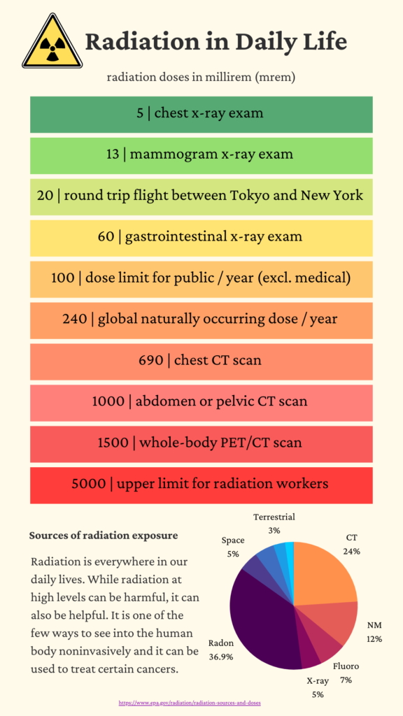
| Doses from Medical Imaging Procedures | |
| Procedure | Dose (mrem) |
| X-Rays-single exposure | |
| Pelvis | 70 |
| Abdomen | 60 |
| Chest | 10 |
| Dental | 1.5 |
| Hand/Foot | 0.5 |
| Mammogram (2 views) | 72 |
| Nuclear Medicine | 400 |
| CT | |
| Full body | 1,000 |
| Chest | 700 |
| Head | 200 |
To put the values into perspective, the background radiation dose for a typical human is ~ 3 mSv / yr.
There is no clear evidence of harm for doses below about 100 mSv, but in medicine, it is typically assumed that any dose may result in stochastic effects, with the likelihood of the effect proportional to the dose.
ALARA
Radiation exposure should be kept as low as reasonably achievable (ALARA) through proper radiation protection measures, such as shielding, distance, and time limitations. Radiation is used in medicine when the information or treatment effects from the radiation outweigh the harm caused. For example, after severe head trauma, it may be worth a few mSv of dose if it means being able to determine the extent of bleeding in the brain.
Shielding is typically done with lead and concrete. Technologists will stand behind leaded glass while an x-ray or CT scan is performed. Distance is used by technologists by staying farther away from radiation sources. Time is used to limit the number of photons someone is exposed to.
Specialized x-ray techniques and clinical applications
Digital subtraction angiography (DSA)
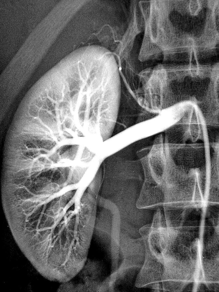
DSA produces high-resolution images of small blood vessels. First a regular x-ray image is acquired, followed by injection of contrast and another x-ray image.
Subtracting the images allows one to only see vessels (where the contrast is flowing through). It is useful for identify blood clots, vessel stenosis, arteriovenous malformations (AVM) among others.
Mammography
Mammography is used to detect small tumors or microcalcifications in breast tissue.
Special low-energy x-ray tubes are used with Molybdenum (instead of Tungsten) target. These generate mostly characteristic x-rays around ~20 keV. Lower x-ray energies are possible because the target is thin (breast tissue is highly compressed during the study), and it results in a lower dose prevent radiation-induced cancers, since they are used for regular screening tests for breast cancer. The compression of breast tissue not only improves x-ray transmission but also minimizes scatter and improves image quality.
Fluoroscopy
Fluoroscopy uses a continuous or pulsed x-ray exam and typically only planar images. It is used for interventional procedures or for dynamic studies. Because multiple images are take over time, it is possible to capture respiratory motion, the movement of contrast through GI/cardiovascular, or the placement of a cardiac catheter. Because of the multiple images, it can deliver very high dose to patient and operators. It is important to monitor patient skin dose (amount of time beam is on). Operators wear lead aprons and thyroid shields to protect themselves. In addition, the X-ray tube is usually places below couch to limit dose from head leakage to staff.
Clinical and Radiation oncology applications
Diagnostic radiology has many applications, e.g.:
- Determine presence of bone fractures
- Detect pneumonia, lung tumors, tuberculosis, congestive heart failure
- Vascular imaging using DSA
- Diagnose GI tract diseases by fluoro with contrast
- Screen for breast cancer
- Urinary tract investigations (kidney stones, etc)
- Detect and locate foreign bodies
In radiation oncology, x-ray imaging is used for 2D treatment plan design (e.g., palliative, whole brain). It is also used for setup images to confirm bony alignment, although CT is most common today.
